What Are the Functions of Motherboard Ports and Headers?
By Lindas Wu|July 28,2026
Motherboards
A motherboard acts as the central nervous system of your PC, routing power and communication signals between the processor, memory, graphics card, and storage. Understanding its onboard ports and headers is a crucial task to ensure every component is correctly connected and functions at peak performance without hardware conflicts. From the simplest and most vital power connectors to advanced, feature-rich overclocking utilities, this comprehensive port guide will ensure a smoother and more enjoyable PC DIY journey, whether you are building with an AMD or an Intel-based MSI motherboard.
Onboard Power & Cooling Connectors
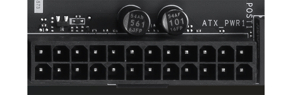
ATX_PWR (24-pin): Connects to the Power Supply Unit (PSU) to deliver main power to the motherboard.
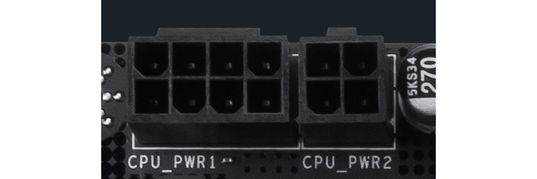
CPU_PWR (8-pin or 4-pin): Provides dedicated power to the CPU; requires the connection of CPU power cables.
CPU_FAN: Dedicated header for connecting the CPU cooler fan.
PUMP_SYS: Dedicated header for connecting liquid cooler pump fans or system fan.(formerly designated as PUMP_FAN).
SYS_FANX: Supports 2Acooling fans. SYS_FAN: Supports standard 1A cooling fans.
Storage & Lighting Connectors
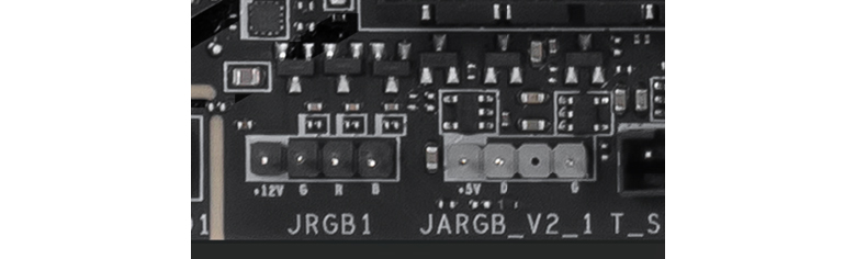
SATA: Connects to HDD storage devices. JRGB (4-pin): Connects to 12V RGB devices featuring single-color RGB lighting effects. JRAINBOW (3-pin): Connects to 5V ARGB devices featuring addressable color lighting effects. JARGB_V2 (3-pin): The upgraded 5V ARGB header not only connects addressable color lighting effects but also supports Gen 2 LED devices, allowing individual customization of each LED bead. .
Front Panel Connectivity
FP1: Connects front panel chassis elements, including the power switch, reset switch, power LED, and HDD LED. JFP2: Connects the front panel chassis buzzer/speaker. JUSB (9-pin): Connects front panel USB 2.0 Type-A ports.
JUSB (19-pin): Connects front panel USB 5Gbps Type-A ports. JUSBC: Connects front panel USB Type-C ports.
PD_PWR1: Supplemental power input required to enable USB Power Delivery (PD) fast charging for the front panel Type-C port. JAUD1: Connects front panel audio elements, including headphone and microphone jacks. JCI1: Connects to the chassis intrusion sensor, triggering an alert mechanism to notify the user if the case is opened.
MSI EZ DIY Interfaces
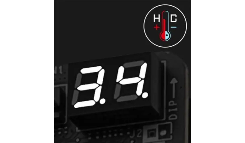
POST1: The EZ Digi-debug LED function displays debug codes to diagnose motherboard issues (e.g., 55 for memory sequencing error/loose installation, 00 for CPU not detected).
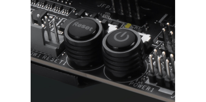
POWER1: Onboard power button used to boot the system when tested outside a chassis. RESET1: Onboard reset button used to reboot the system when tested outside a chassis.
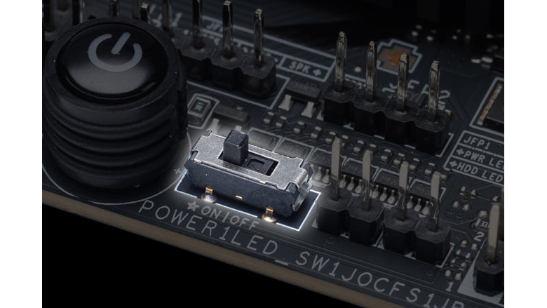
LED_SW: A physical toggle switch used to turn all onboard LED lighting on or off.
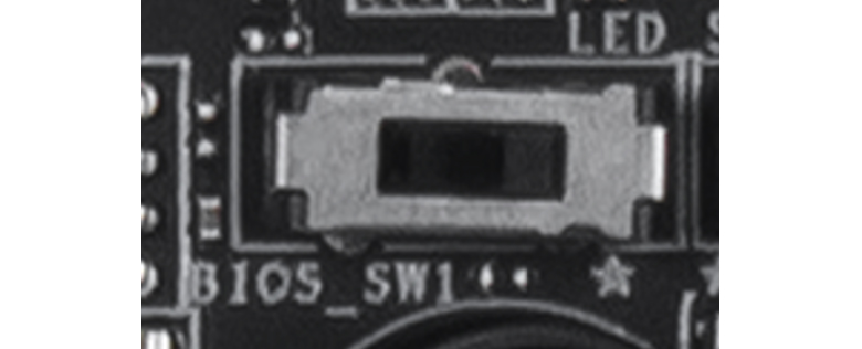
BIOS_SW: The EZ Switch function enables quick and effortless switching on models equipped with Dual BIOS.
JAF_1: The EZ Conn header is designed for compatibility with MSI liquid coolers; integrates fan and RGB connections into a single cable to simplify cable routing and ease installation.
JAF_2: The EZ Conn header is designed for compatibility with MSI liquid coolers; integrates fan, RGB, and USB connections into a single cable to simplify cable routing and ease installation.
JTBT5: Connects to the MSI Thunderbolt 5 expansion card. JTPM: Connects to a discrete TPM 2.0 module. Note: Recent processors feature built-in firmware TPM (fTPM 2.0), making an external JTPM connection optional for most users.
Advanced Overclocking & Safety
The following headers feature advanced overclocking capabilities. Designed by MSI for extreme overclocking enthusiasts, these headers are typically found on high-end motherboards such as UNIFY and ACE, and are not available on all models.
JBCLK1 / JBCLK2: Base clock adjustment pins. Shorting these two pins with a metal object allows real-time adjustment of the motherboard's overclocking frequency.
JBAT1: Clears BIOS settings/CMOS by shorting these two pins with a metal object for a few seconds. PCIE_PWR1: Provides supplemental power to PCIe slots, ensuring stability when graphics cards (GPUs) face high power draws.
JOC_FS: Safe Boot function. Shorting these two pins forces the system to boot with BIOS default safe parameters. JOC_RT: Shorting the two pins allows the system to reboot and perform hardware diagnostics using the current overclocking settings. JSLOW: Shorting the pins forces the frequency to decrease during extreme overclocking. JLN: Liquid Nitrogen (LN2) extreme overclocking mode header. Once shorted, it relaxes built-in protection limits, allowing the motherboard to post and boot under sub-zero temperatures. JPWRLED: Power demonstration header. Connecting a 2-pin cable to an external charger illuminates onboard RGB lighting without connecting the main PSU. JDASH1: Designed for onboard displays and devices like the UNIFY series Tuning Controller. Once connected, it enables real-time hardware overclocking, voltage adjustment, and CPU status monitoring without entering the BIOS. W_FLOW: Connects to a water flow meter to monitor liquid velocity inside custom water cooling loops. T_SEN: Connects to a thermistor cable to monitor the temperature of specific targeted objects or areas. J1 / J2 / JT1 / JF1 / JDP1 / JTP1: Internal factory testing and debugging pins; standard users do not need to connect any cables to these headers.